Load Test on 3 Phase Alternator
Set the voltage control knob at it full counter clockwise position. Hi All I have a curious question which I am facing in real life.

Voltage Regulation Of Alternator By Emf Method And Solved Problem Alternator Ruse Emf
LOAD TEST ON THREE PHASE ALTERNATOR 1.

. 9 No load and blocked rotor test on 1-phase induction motor. If the alternator can be removed from the bike and disassembled you may also want to do a Megger test of the stator winding. Using three point starter the motor is started.
The terminal voltage of an. Open Circuit Characteristics of an alternator PROCEDURE Load Characteristics 1. Testing only three phase delta you would use three loads all wired phase to phase.
The Effect of Load Changes on a Synchronous Generator Operating Alone. To Study and Measure Positive Negative and Zero Sequence Impedance of a Alternator 5. A Perform load test on 3-phase induction motor.
Connect the circuit as shown in figure. Load test on three phase alternator using Virtual Labvirtuallab alternator loadtest. Whenever the load on the alternator is varied the terminal voltage will also vary.
Regulations on 3-phase salient pole alternator by Slip test. Rheostat is used as a potential divider. Because the stator MMF has such a main effect on the magnetic flux the voltage regulation of alternators is fully poor and the dc field current must be continuously adjusted to keep the voltage constant under changeable load conditions.
It is used to increase or decrease the stator voltage of DC shunt motor. Testing as shown you would use a single load. B Compute Torque Output power Input power Efficiency Input power factor and Slip for every load setting and to determine how speed efficiency power factor stator current torque and slip of an induction motor vary with load.
An alternator works as a generator when its rotor carrying the field system is rotated by a prime-mover which in this case is DC shunt motor. Vary the load in steps and note down the corresponding load current and. Let us take a look at all those reasons in detail.
There are AC output and 12v DC direct output types. The most commonly used machine for generation of electrical power for commercial purpose is the synchronous generator or alternator. Connections are given as per circuit diagram.
The machine which produces 3-phase power from mechanical power is called an alternator or synchronous generator. 5 Load test on 3-phase induction motor. The simplified schematic of figure 1 view A shows all the windings of each phase lumped together as one winding.
Note down the name plate details of motor and alternator 2. Couple the Synchronous motor with Squirrel cage induction motor by belt. D Open the three resistance load switches for no load on the alternator and measure and record the no load E1 and I 2.
Open Circuit Test on Three Phase Alternator 1 Close the DPST Double Pole Single Throw switch connecting the armature winding of DC shunt motor to supply. Determine the full load regulation of a three phase synchronous generator by synchronous impedance method 3. If a single phase of a three-phase alternator is heavily loaded its voltage will be reduced due to the IR and IX L drops in the stator.
The DPST is closed on supply side. Load test on 3-Φ alternator resistive load 0-10a mi 10a 290Ω2a 0-600vmi 10a name plate details 10a v415v i65a 0-1amc 290Ω2a n1500rpm p11 kva exc. The rotor is omitted for simplicity.
The three-phase alternator as shown in this schematic is made up of three single-phase. 7 Separation of losses in three-phase induction motor. Supply d p s t s fuse fuse l1 l2 f a a1 a2 m f1 f2 - dc shunt motor a 220 v dc.
There are either 3 wire or two wire systems and the tests will be. Synchronization of two Three Phase Alternators by. 220v 11a fuse rating 125 of rated current 125100 x 6510a 10a 220 v dc.
Voltage drop due to armature resistance IR a Voltage drop due to armature leakage reactance IX L and Voltage drop due to armature reaction. 6 No load and blocked rotor test on 3-phase induction motor. Set the resistive load knob at it off position.
The Three phase resistive load is connected to the Alternator output terminals with the load switches in off condition. Hello all This video is about Experiment of load test on the three phase alternatorI have done this experiment in virtual lab045 Aim and theory239 Proce. The voltage waveforms generated across each phase are drawn on a graph phase-displaced 120º from each other.
This variation in terminal voltage is mainly due to three reasons. These days 3-phase ac. To Study and Measure Direct and Quadrature Axis Reactance of a 3 phase alternator by Slip Test 4.
Supply fuse fuse - d p s t s f1 f2 synchronous. The alternator is brought to Rated speed by varying motor. 4 V and inverted V curve of synchronous motors.
LOAD TEST ON THREE PHASE INDUCTION MOTOR AIM. Measure and record the full load I 1 I 2. Testing a 3 Phase alternator Stator Engine and key off static test.
I need to feed 250A from a diesel generator set to an equipment under test. Load Test on Three Phase Alternator - You can try with inductive and Capacitive type load. 8 Load test on 1-phase induction motor.
Adjust the dc excitation of the alternator until the output voltage E1 208 Vac. This article will focus on the AC type. Remember to check the motor speed and readjust to 1800 rmin if required.
System is being exclusively used for generation transmission and distribution of power. Load Test on Three Phase Alternator. The Alternator is kept at rated voltage output and made to run at rated rpm from the DC motor.
Plot the graph between load terminal voltage and load current.

Multiply Excited Magnetic Field Systems Eeeguide Com Magnetic Field Magnets Excited

Pin On Equipment

1 Wire Alternator Wiring Diagram Wiring Forums Alternator 8n Ford Tractor Ford Tractors

Simulation Of The Airflow Around A Wind Turbine Https Www Simscale Com Projects Jprobst Simulation Of The Airflow Ar Wind Turbine Free Energy Generator Wind

3 Phase Power Systems Have Numerous Advantages Compared To Single Phased Systems Such As Lower Conductor R Electronic Engineering Power To Weight Ratio System

564 Me Gusta 1 Comentarios Electrical Page Electrical Page En Instagram Follow The Electrician Offic Electricity Induction Electronic Engineering

Perkins 2800 Series 600 Kva Project Pp Precast Telkomsel Renon Bali
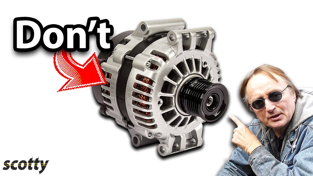
51 This Alternator Will Destroy Your Car Youtube Car Life Hacks Alternator Car Alternator
Control Panel Wiring Diagram Pdf Electrical Circuit Diagram Electrical Panel Wiring Electrical Wiring Diagram

Pin On Electronics Circuit

How To Wire 3 Way Dimmer Dimmer Switch Light Switch Wiring Dimmer

Pin On Vrije Energie

Voltage Regulation Of Alternator By Direct Loading And Solved Problem Alternator Directions Regulators

General Electric T 64 Aircraft Engine Programmed Training Course Manual General Electric Training Courses Aircraft Engine

Why Generator Rated In Kva Not In Kw Solar Power Inverter Generator Electronic Schematics

Squirrel Cage Induction Motor Animation Squirrel Cage Induction Squirrel

Voltage Regulation Of Alternator By Direct Loading And Solved Problem Alternator Directions Regulators

Pin On Electronics Circuit

564 Me Gusta 1 Comentarios Electrical Page Electrical Page En Instagram Follow The Electrician Offic Electricity Induction Electronic Engineering


Comments
Post a Comment